
GST : 27AAFFV7667M1ZA

Call us
08045801431
Call us
08045801431

For global buyers, choosing a Variable Frequency Converter means more than matching its rated power to a motor. Supply voltage, input frequency, phase, enclosure, and control options all need to fit the installation. A unit designed for a 50 Hz supply may require different configuration on a 60 Hz network. Check the motor nameplate. Small details matter. Cable length, heat, dust, and starting torque can also influence everyday performance. A converter that looks suitable on paper may prove difficult to commission or maintain.
This guide compares seven options through practical buying considerations, including power range, operating features, protection, documentation, and service availability. The aim is to help readers identify models worth further evaluation, not to declare one choice best for every application. Review the manufacturer’s specifications and confirm compatibility with the motor, load, and site conditions before purchasing. Regional voltage standards, installation practices, and local compliance requirements may affect the final decision. Ask suppliers about technical support and replacement parts. That can save time later. Product information can change, and published specifications do not reveal every commissioning challenge. A shortlist is only a starting point. Careful checks with a qualified installer remain important, especially where equipment must run continuously or control demanding loads.
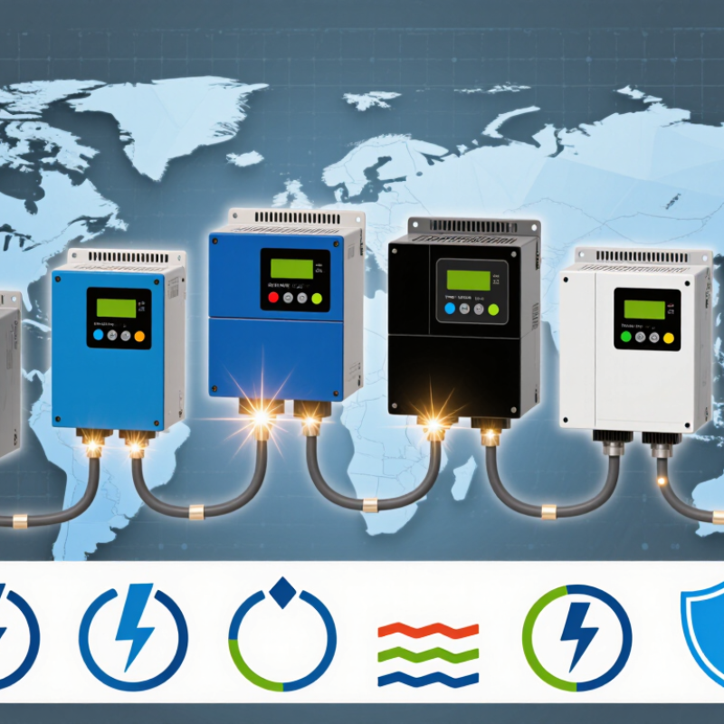
A variable frequency converter changes the speed of an AC motor by controlling the frequency and voltage of its electrical supply. Inside, a rectifier converts incoming AC power into DC. A capacitor-stabilized DC bus then feeds an inverter, which switches the power rapidly to create AC at a selected frequency. The motor’s rotating magnetic field follows that frequency, changing shaft speed. In practice, a pump may slow from full flow instead of wasting energy across a partly closed valve. The relationship is useful, but not perfectly simple. Motor load, cooling, and control settings all affect performance.
The International Energy Agency’s 2011 report, Energy-Efficiency Policy Opportunities for Electric Motor-Driven Systems, estimated that these systems use about 45% of global electricity. That figure describes motor-driven systems, not savings from converters. Still, it shows why matching motor speed to demand matters. A converter can reduce energy use in variable-load applications, though results depend on the system and operating hours. At low speeds, some motors may need extra cooling. Poorly configured controls can also cause vibration or unwanted electrical noise. A careful assessment should check the motor nameplate, load profile, wiring, and operating environment before selecting a converter.
A variable frequency converter (VFD) controls an AC motor’s speed by changing the frequency and voltage supplied to it. In a typical drive, a rectifier converts incoming AC power to DC, a DC bus smooths and stores that energy, and an inverter switches the DC into variable-frequency AC, commonly using pulse-width modulation (PWM). For an induction motor, synchronous speed is determined by frequency and pole count: RPM = 120 × frequency (Hz) ÷ number of poles; actual operating speed is usually lower because of motor slip.
| Converter Type | Typical Supply and Output | Control and Operating Characteristics | Best Suited For | Key Buying Considerations |
|---|---|---|---|---|
| 1. General-Purpose Low-Voltage VFD | Commonly available for standard low-voltage AC systems, including nominal 200–240 V and 380–480 V classes. Input and output phase configurations depend on the drive. | Usually provides basic V/f control, adjustable acceleration and deceleration, and common motor protection functions. | Fans, pumps, conveyors, and other applications with relatively straightforward speed-control requirements. | Match the drive’s rated output current to the motor nameplate current and account for load type, ambient temperature, enclosure, and overload requirements. |
| 2. Single-Phase-Input, Three-Phase-Output VFD | Accepts single-phase input and supplies variable-frequency three-phase output on models designed for that arrangement. Availability and ratings vary by voltage class. | Provides speed control for a three-phase motor where a suitable three-phase supply is unavailable. | Small workshops, light-duty machinery, and locations with single-phase utility power. | Not every drive supports single-phase input. The manufacturer may require derating; check the permitted input wiring, input-current demand, and motor compatibility. |
| 3. Sensorless Vector-Control VFD | Typically offered in low-voltage classes with variable-frequency AC output for compatible three-phase motors. | Uses a motor model and electrical measurements to estimate motor behavior without a shaft encoder, generally improving low-speed torque control over basic V/f control. | Conveyors, mixers, and other loads that need better torque response without encoder installation. | Motor identification or tuning may be needed. Performance depends on the drive, motor data, and operating conditions; it is not the same as encoder-based feedback. |
| 4. Closed-Loop Vector-Control VFD | Available in drive families that support encoder or other compatible motor feedback devices. | Uses feedback to regulate motor speed more closely, especially at very low speed or during changing loads. | Hoists, winders, and applications requiring precise speed regulation or controlled low-speed operation. | Requires compatible feedback hardware, correct installation, and commissioning. Confirm the drive’s feedback interface and safety requirements. |
| 5. Pump-and-Fan Application VFD | Generally supplied in low-voltage ratings matched to the motor and site electrical system. | May include application functions such as sleep and wake, multi-pump control, or process feedback; features differ by model. | Variable-flow or variable-airflow systems where motor speed can follow demand. | Confirm compatibility with the pump or fan system, pressure or flow sensor, bypass needs, and minimum-speed limits. Energy savings depend on the system and operating profile. |
| 6. Medium-Voltage VFD | Designed for medium-voltage motors; common system classes include approximately 2.3–13.8 kV, depending on the product and region. | Uses a topology engineered for medium-voltage conversion and typically requires project-specific engineering and commissioning. | Large pumps, compressors, fans, and other high-power industrial machinery. | Assess utility supply, motor insulation, harmonics, cooling, protection, installation space, and service support. Voltage class and rating must be confirmed for the actual site. |
| 7. Regenerative VFD | Available in certain low- and medium-voltage drive systems, depending on the required rating and configuration. | Can return suitable braking energy from the motor to the electrical supply through a regenerative front end, rather than dissipating all of it as heat in a braking resistor. | Frequent deceleration, overhauling loads, test stands, and multi-axis systems with recurring braking energy. | Regeneration requires compatible equipment and a suitable supply connection. Compare energy duty, harmonics, braking performance, and system cost before selection. |
Selection note: “Best” depends on the motor, load, supply, control accuracy, environment, and local electrical requirements. Voltage classes, available features, and ratings vary by manufacturer and market; verify the drive and motor documentation before purchase or installation.

 Send Inquiry


