
Choosing the top Digital Signal Isolator in 2026 is not simply a matter of comparing data rates. Engineers must weigh isolation voltage, timing accuracy, channel count, power use, package size, and the application’s safety requirements. A compact four-channel device may suit a motor-control board, while a high-speed part may better fit an isolated data interface. The wrong trade-off can mean extra board space, excess heat, or unreliable signal timing.
The broader semiconductor market shows why these choices matter. The Semiconductor Industry Association, citing World Semiconductor Trade Statistics, reported global semiconductor sales of $627.6 billion in 2024, up 19.1% from 2023. That figure covers the whole chip industry, not isolators alone, so it should not be mistaken for a market-size estimate for this component category. Still, it reflects the expanding scale of electronics used in computing, vehicles, industrial equipment, and communications. Small components matter.
This guide compares leading digital isolators through measurable specifications and practical design considerations. It examines isolation ratings, common-mode transient immunity, propagation delay, and operating conditions, while distinguishing manufacturer claims from application needs. Datasheet figures are useful, but they do not tell the whole story. Board layout, temperature, and the surrounding circuit can change real-world performance. Rankings also depend on the design brief; a universal winner is unlikely. The goal is a clearer shortlist, not a substitute for checking current datasheets, certification details, and system-level requirements before selection.
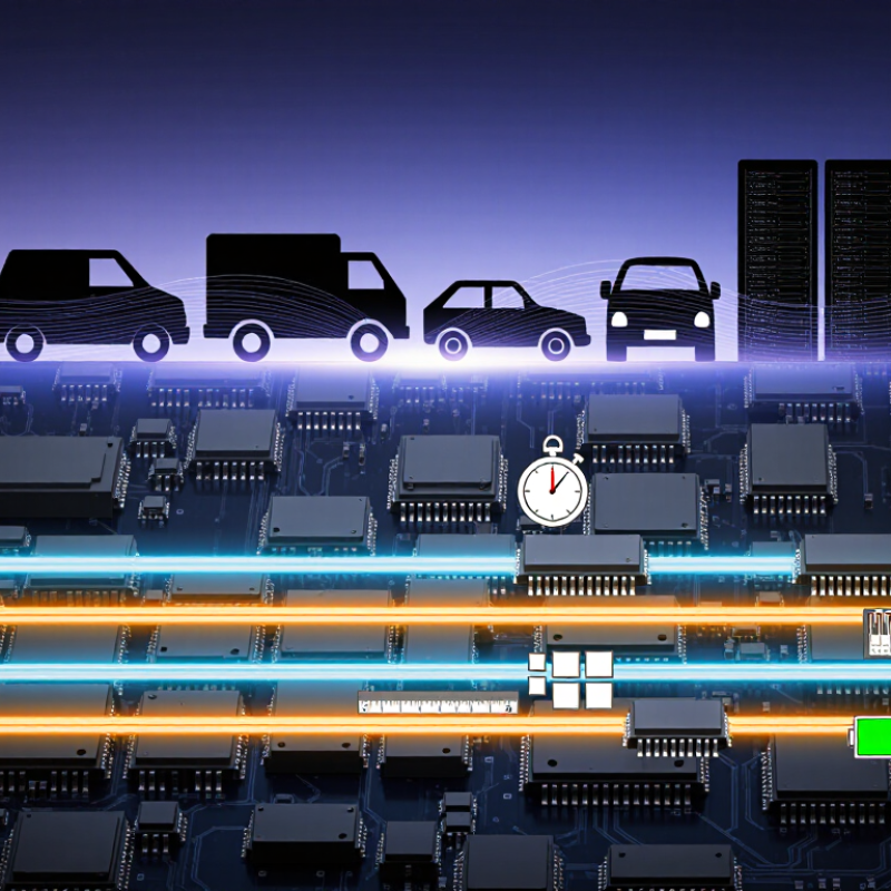
Digital signal isolators transfer logic signals across an electrical isolation barrier without a direct conductive connection. Inside, capacitive or magnetic coupling carries changing data between separate circuit sides. A controller can send a clock or sensor reading while remaining electrically separated from the receiving circuit. That separation helps reduce ground-loop problems and limits how much fault voltage can reach sensitive electronics.
The barrier is not a shield against every surge. Its insulation rating, creepage distance, signal speed, and operating conditions all matter. For example, a fast data link may need an isolator with sufficient bandwidth and low timing distortion. A design can look safe on paper and still fail if board layout or component ratings are overlooked. That detail deserves a second check.
Tips: Compare the isolator’s working-voltage and transient ratings with the actual circuit conditions. Keep high- and low-voltage traces separated as the design requires, and check the datasheet’s timing limits. Test the assembled circuit under realistic loads. Small layout choices matter.

A digital signal isolator transfers a logic signal between two circuits without a direct conductive connection. Imagine a controller sending a switching command across a narrow barrier to a motor-side circuit. The bits cross; the grounds do not. Inside the isolator, capacitive, magnetic, or optical coupling carries the changing signal across that barrier. Separate power supplies may still be needed on each side.
That separation can help limit ground-loop currents and keep some electrical disturbances from reaching sensitive electronics. It is not a cure-all. Barrier voltage ratings, creepage and clearance distances, and common-mode transient immunity must suit the actual design. Fast edges matter, too: stray capacitance can let brief disturbances couple across the barrier. Small details count. Isolation also does not automatically protect every connected component or replace sound board layout. I would check the datasheet carefully; a rating alone can be easy to misread.
Tips: Match the isolator’s channel direction and data rate to the signal. Check startup behavior, propagation delay, and required supply voltages on both sides. Keep isolated traces separated as specified, and avoid routing noisy signals beside them. Test the assembled circuit under realistic switching conditions. Bench results may surprise you. Revisit the layout if noise persists.
Digital signal isolators transfer logic signals across a galvanic isolation barrier without a direct conductive connection. The options below compare common isolation approaches and use cases; actual ratings depend on the specific device and package.
| Isolation approach | How it works | Where it fits best | Key advantages | Trade-offs and checks |
|---|---|---|---|---|
| Capacitive digital isolator | Encodes logic transitions and transfers them through a capacitive barrier. | Fast SPI, ADC and control-signal links in industrial, energy and instrumentation systems. | Supports high-speed digital signaling and compact multichannel integration; the barrier has no direct conductive path. | Check working voltage, isolation rating, creepage and clearance, common-mode transient immunity, channel direction and fail-safe output behavior. |
| Magnetic digital isolator | Transfers encoded signals across the barrier using magnetic coupling, commonly with integrated micro-transformer structures. | Isolated digital control and data links where fast edges and strong transient performance are needed. | Can provide high data rates and robust rejection of fast common-mode voltage changes when the device is appropriately specified. | Review the specified transient immunity, isolation lifetime, emissions and susceptibility in the intended circuit layout. |
| Optocoupler | Uses an LED to transmit light across an insulating gap to a photosensitive detector. | Legacy-compatible designs, low-to-moderate-speed control, and circuits where optical isolation is specifically preferred. | Provides optical signal transfer and a well-established isolation approach across many application areas. | Check propagation delay, channel-to-channel matching, LED drive requirements and current-transfer-ratio variation over temperature and operating life. |
| Isolated interface transceiver | Combines a digital isolation barrier with a physical-layer interface, such as an isolated differential bus transceiver. | Connecting a controller to an isolated field bus when both signal isolation and bus-line driving are required. | Reduces external component count by integrating isolation and interface functions in one device. | Confirm protocol compatibility, bus speed, termination needs, isolation rating, supply arrangement and fault-protection features. |
| Isolated gate-driver signal path | Transfers control signals across an isolation barrier and conditions them to drive power-switch gates. | Power converters, motor drives and other circuits using isolated MOSFET or IGBT gate control. | Can combine signal isolation with gate-drive functions such as undervoltage lockout and fault reporting. | Check peak output current, propagation-delay matching, default output state, insulation ratings and the required isolated power supply. |
Selection note: “Best” depends on the application. Compare the device’s working voltage and transient ratings with the system requirements, and verify safety certification, package creepage and clearance, timing, power consumption and layout guidance in its datasheet.
When comparing digital signal isolators, begin with the signal, not the headline isolation voltage. Check maximum data rate, propagation delay, channel-to-channel skew, and pulse-width distortion against your actual interface. For example, a 10 Mb/s control link may tolerate more delay than a tightly timed SPI bus. Leave margin for clocking and board-level noise. Numbers can mislead.
Isolation ratings need careful reading. IEC 60747-17:2020 addresses magnetic and capacitive couplers, while IEC 60664-1:2020 uses factors such as overvoltage category and pollution degree in insulation coordination. That distinction matters: a short-duration withstand rating is not the same as continuous working voltage. Compare working voltage, surge withstand, creepage, clearance, and common-mode transient immunity (CMTI) as separate specifications. A high CMTI figure can help when fast voltage edges appear across the barrier, but it does not replace sound layout.
Also inspect power and failure behavior. Compare supply-current figures at your intended data rate, startup defaults, output state during power loss, and temperature range. Check whether stated timing and isolation values apply across the full operating range. In bench testing, probe both sides during switching; ringing and ground bounce can expose weaknesses that a datasheet table does not. I still find this part easy to underestimate. Select from the end application’s requirements, and verify the final board against the relevant insulation standards.
In 2026, leading digital signal isolators are best compared by application, not headline speed. For inverter gate-control boards, high common-mode transient immunity and dependable isolation can matter more than extra channels. Compact capacitive isolators suit fast, space-limited interfaces, while magnetic designs may fit noisy switching environments. Optical isolation remains useful where strong separation is valued, though size and power needs can be trade-offs. Check channel direction and fail-safe output behavior.
For industrial sensors and control systems, compare data rate, propagation delay, channel-to-channel skew, temperature range, and package footprint. Review both the working-voltage rating and the isolation certification; a brief withstand-voltage figure does not mean the device can operate continuously at that level. Also check creepage and clearance against the board layout and system requirements. Bench-test on the actual board. I would not choose by peak data rate alone; that shortcut can miss startup behavior, supply-current limits, or output glitches during power-up. A small detail, but worth testing.
Selecting a digital signal isolator starts with the circuit’s real operating conditions, not a headline rating. Check the working voltage, transient exposure, and required isolation level separately. A short-duration withstand figure does not describe safe continuous operation. Read the datasheet carefully.
For a motor drive or inverter, prioritize strong common-mode transient immunity. Fast voltage swings can corrupt signals even when the data rate seems modest. For a communication link, match the isolator’s maximum data rate and channel direction to the interface. A control board may need several channels, while a sensor input may need only one. Extra channels can add cost and board area.
Power and layout matter too. Some isolators need an isolated supply on one side; others integrate power, which can simplify wiring but affect heat and noise. Check propagation delay when timing is tight, and review operating temperature for equipment near warm enclosures. In practice, tidy comparison tables can mislead. Test the candidate in the actual circuit, with representative switching edges and cable lengths. For medical or industrial equipment, confirm the end product’s applicable safety requirements with qualified design review. Datasheet details are useful. Bench results are better.
I²C mode clock rates range from 100 kHz in Standard-mode to 3.4 MHz in High-speed mode. Choose an isolator that supports the required rate, and also check propagation delay, timing margins, and the rise-time effects of the bus and its pull-up resistors. These figures are I²C mode rates, not guaranteed isolator data rates.
For an immediate response, please call this
number08045801431
Price:
