How to Use Flexible PCBs in Electronic Design?
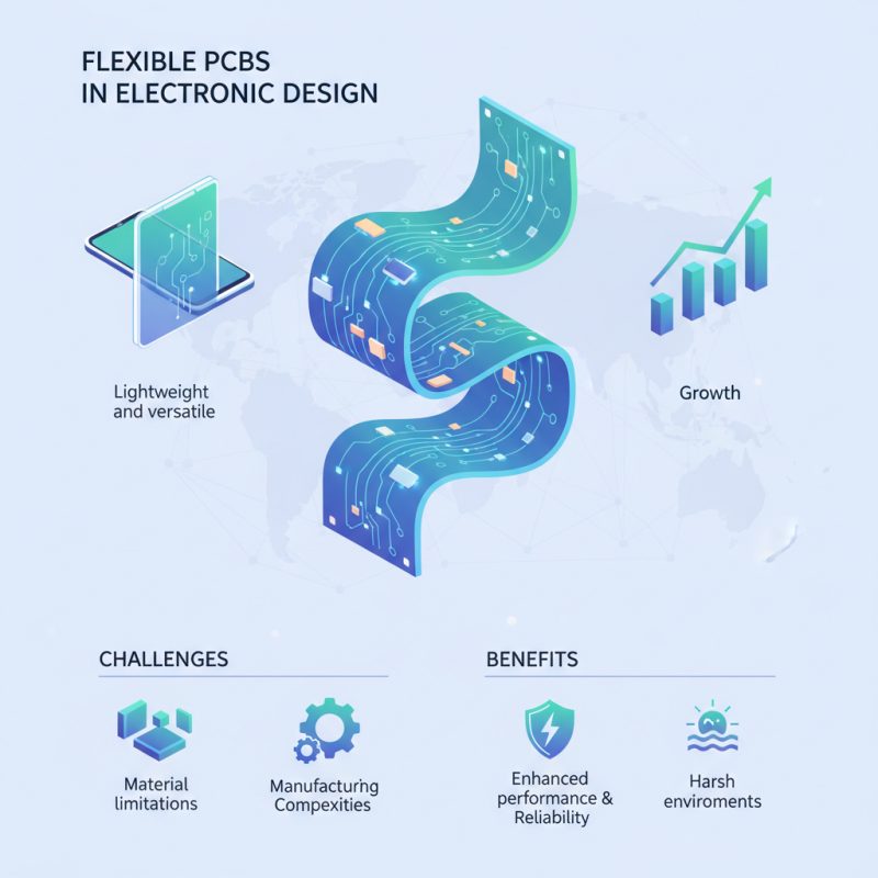
Flexible Pcbs have revolutionized electronic design, offering unique advantages in various applications. The global flexible PCB market is projected to reach $30.2 billion by 2027, reflecting a CAGR of 10.1% from 2020. This rapid growth indicates a rising demand for lightweight and versatile circuit solutions. Flexible PCBs enable devices to be thinner and more compact, accommodating modern design requirements.
Incorporating flexible PCBs into electronic design is not without its challenges. Engineers often face issues such as material limitations and manufacturing complexities. It’s crucial to select the right substrate materials, as they impact both performance and durability. Furthermore, designing for flexible PCBs requires a shift in traditional practices, which can be daunting for many.
Despite these challenges, the potential benefits are significant. Flexible PCBs can enhance device performance and reliability. They withstand harsh environments better than rigid alternatives. As industries increasingly embrace innovation, navigating the complexities of flexible PCB usage will be essential for success. Adapting to these changes may require ongoing learning and adjustments in engineering strategies.
Understanding Flexible PCBs: Basics and Applications
Flexible printed circuit boards (PCBs) are revolutionizing electronic design. They are lightweight and adaptable. Designers often find them beneficial for unique applications. Flexible PCBs can fit into tight spaces where traditional rigid boards cannot. This flexibility opens new avenues for innovation.
One common application is in wearable devices. Many wearables rely on flexible PCBs for comfort and seamless integration. They can bend and contour to the human body. However, the design process can be tricky. Engineers must consider material choices and layer structures carefully. Mistakes can lead to failures in performance or durability.
Another area is in automotive electronics. Flexible PCBs are used for sensors and lighting systems. They help reduce weight and space in vehicles. Yet, the harsh conditions can challenge their reliability. Testing is crucial to ensure they can withstand extreme temperatures and vibrations. There is always room for improvement in designs. Reflecting on past projects helps refine future ones.
Key Advantages of Using Flexible PCBs in Electronic Design
Flexible PCBs have become a game-changer in electronic design. Their adaptability allows for more compact and lightweight products. Designers can create complex shapes without sacrificing performance. This flexibility opens up new avenues for innovation in consumer electronics and industrial applications.
One significant advantage of flexible PCBs is their durability. Unlike rigid boards, they withstand bending and twisting. This quality is essential for wearable technology. Devices can be lighter and more comfortable to wear, enhancing user experience. Thin profiles make integration easier, especially in tight spaces.
Tips: Consider the design limitations when using flexible PCBs. Ensure that the bending radius meets the manufacturer's specifications. Testing prototypes in real-world conditions is critical. Flexibility can lead to challenges in component placement, so plan carefully. Remember, mistakes in layout can lead to failures. It’s crucial to rethink your design approach to optimize performance.
Design Considerations for Flexible PCBs
When designing with flexible PCBs, several crucial factors come into play. Thickness matters; thinner materials often allow for better flexibility. However, thinner boards may lack rigidity. This can impact performance under stress. Designers must balance flexibility and strength when choosing materials.
Additionally, consider the environment in which the PCBs will operate. High temperatures and humidity can degrade some materials. This deterioration may not be immediate, yet it affects long-term reliability. Proper testing is vital to ensure that the selected materials withstand these challenges.
Connection points deserve attention too. Solder joints on flexible substrates can be sensitive. They are prone to cracking under movement. Designing for these connection points requires careful planning. Standard methods might not provide the needed durability. Alternative soldering techniques should be explored, reflecting the unique challenges of flexible designs.
Manufacturing Processes for Flexible PCBs
Flexible printed circuit boards (PCBs) are gaining traction in various sectors. Their unique attributes, such as being lightweight and adaptable, make them ideal for compact and intricate designs. The manufacturing process for flexible PCBs involves several key steps. These steps include material selection, layer stacking, and etching. Each stage demands precision and attention to detail.
Manufacturers often employ polyimide or polyester films as substrates. According to a recent industry report, the flexible PCB market is projected to exceed USD 35 billion by 2027, driven by the rising demand in consumer electronics and automotive sectors. However, challenges remain. Ensuring consistent thickness during lamination is crucial. Variability can lead to complications in circuit integrity and performance.
Etching and surface treatment are critical to achieving desired electrical properties. Moreover, the process's environmental impact needs to be considered. Waste generated during production can be significant. Sustainable practices are becoming essential. Manufacturers must focus on reducing their ecological footprint while maintaining high-quality standards. Adapting to these challenges is vital for progress in flexible PCB technology.
Usage of Flexible PCBs in Different Applications
Best Practices for Testing and Integrating Flexible PCBs
Flexible PCBs offer unique advantages in electronic design, but testing and integration require careful planning. According to an industry report, about 30% of failures in flexible PCBs result from inadequate testing methods. To avoid costly mistakes, you must establish rigorous testing protocols. This includes mechanical stress testing, electrical testing, and thermal cycling tests. Each test reveals different aspects of the PCB's functionality, ensuring reliability in various environments.
Tip: Always prototype with small batches. Small-scale testing can uncover design flaws early. Often, adjustments can save costs in the long run. Flex circuits are susceptible to damage when flexed. Therefore, test designs under actual bending conditions. This helps in verifying durability and performance.
Integration of flexible PCBs into existing systems can present challenges. Often, signal integrity can be compromised due to unexpected bending. An analysis showed that over 40% of design revisions stem from integration issues. Therefore, collaborate with component designers early in the process. Ensure spacing, layout, and rigidity meet the demands of your application.
Tip: Document all testing results meticulously. This creates a valuable reference for future projects, improving efficiency in later designs. Understand that every design iteration offers learning opportunities. Embrace any setbacks as part of the journey to innovation.
How to Use Flexible PCBs in Electronic Design? - Best Practices for Testing and Integrating Flexible PCBs
| Aspect | Considerations | Best Practices |
| Material Selection | Polyimide or PET substrates | Choose materials based on thermal and mechanical requirements |
| Layer Configuration | Single vs. multi-layer | Optimize for space and flexibility |
| Testing Methods | Electrical and mechanical testing | Include flex and thermal cycling tests |
| Integration Challenges | Space constraints and thermal management | Plan layout to minimize heat generation and ensure space efficiency |
| Assembly Techniques | Soldering and adhesive methods | Use appropriate techniques to avoid damage |
| Cost Factors | Material, processing, and tooling | Conduct a cost analysis during the design phase |


 Send Inquiry

