GST : 27AAFFV7667M1ZA

call images

Call us

08045801431

What Is a Hydraulic Solenoid Valve and How Does It Work?

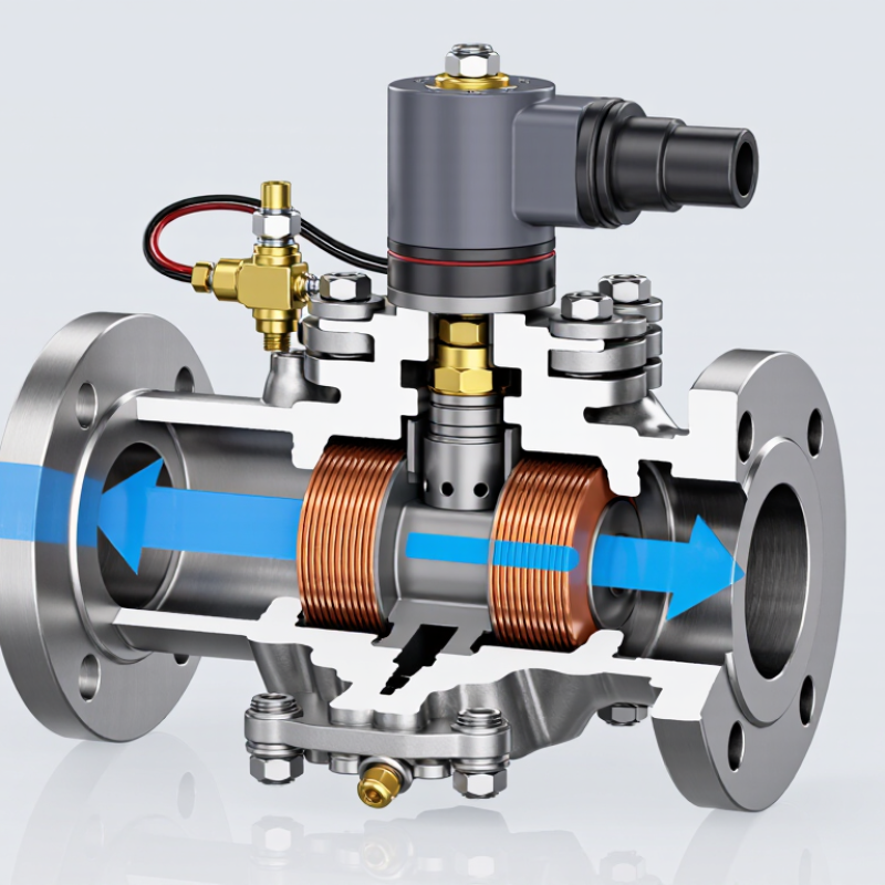
A Hydraulic Solenoid Valve connects electrical control with hydraulic movement. It uses a coil, a magnetic core, and a valve spool or poppet. When electricity reaches the coil, a magnetic field develops. The field pulls the internal armature. That movement opens, closes, or redirects pressurized fluid.

Anthony Esposito, a respected fluid-power author, describes the principle this way: “Fluid power is the transmission and control of energy by means of a pressurized fluid.” His observation explains why the Hydraulic Solenoid Valve matters. It does not create hydraulic power. It controls where that power goes. A small electrical signal can move a cylinder, release a clamp, or shift a motor circuit.

The real operation is visible in practical details. A technician may hear a soft click, check coil voltage, and inspect the spool for contamination. Oil temperature, pressure, wiring, and response time all affect performance. A valve that works perfectly on a clean test bench may hesitate in a dusty machine.

That detail is easy to underestimate.

This article examines how the valve is built, how electromagnetic force changes fluid flow, and how different valve positions affect a hydraulic circuit. It also considers common failures, including burned coils, blocked passages, incorrect voltage, and worn seals. The explanation cannot cover every design. Cartridge valves, directional valves, proportional valves, and pressure-control models behave differently. Still, the basic relationship remains clear: electrical energy commands mechanical movement, and mechanical movement controls hydraulic flow.
What Is a Hydraulic Solenoid Valve and How Does It Work?

What Is a Hydraulic Solenoid Valve?

A hydraulic solenoid valve is an electrically operated component that controls hydraulic fluid inside a machine. It directs pressurized oil through selected passages, helping a cylinder extend or retract, or a motor start and stop. The valve does not create pressure; a pump supplies the flow and pressure it controls. That distinction matters when diagnosing slow or weak movement.

Inside the valve, an electrical coil creates a magnetic field when energized. This field moves a small armature, which shifts a spool or opens a poppet. The change connects or blocks ports such as pressure, tank, and actuator lines. When power is removed, a spring often returns the moving part to its resting position. The response is quick. Still, the exact behavior depends on the valve design and circuit.

In practical use, the valve may sit on a manifold near the machine’s cylinders, with wires leading to a control panel. A faint click can indicate coil movement, but it does not prove that oil is flowing correctly. Contamination, worn seals, low voltage, or a stuck spool can change performance. Even a small fault can matter. Checking the wiring, fluid condition, and system pressure together gives a more reliable picture than replacing the valve based on sound alone.
What Are Its Main Components?

What Is a Hydraulic Solenoid Valve and How Does It Work?

What Are Its Main Components?

A hydraulic solenoid valve uses an electrical signal to move a spool or poppet, directing pressurized fluid through selected passages. Its main components are the coil, armature, return spring, valve body, and internal moving element. The coil creates a magnetic field when energized. This pulls the armature, which shifts the spool or opens the poppet. When power stops, the spring usually returns the parts to their resting position. Simple in principle. But small wear or contamination can affect movement.

The valve body contains ports and carefully machined passages for pressure, return, and actuator flow. Seals help limit leakage, while the electrical connector supplies power to the coil. ISO 4406:2017 classifies hydraulic-fluid cleanliness by particle counts at 4, 6, and 14 μm(c). That standard matters because particles can score close-fitting surfaces or make a spool stick. Tip: Check the valve’s rated voltage, pressure, and flow against the system specifications. Inspect connectors and seals, too. A clean-looking valve is not always clean inside; that is an easy assumption to regret.

How Does the Valve Operate?

When electrical current reaches the solenoid coil, it creates a magnetic field. That field pulls a small armature inside the valve. The armature may move a spool or poppet, changing which internal passages connect. Oil can then flow toward an actuator, return to the tank, or remain blocked. The exact route depends on the valve’s design and port arrangement.

A spring often pushes the moving part back when power is removed. In that case, the valve returns to its default position. Not always: some valves use different spring arrangements, and pilot-operated designs rely on fluid pressure to shift the main stage. Small details matter. A weak electrical supply, dirty oil, or a worn spring can cause slow or incomplete movement. In practice, technicians often check coil voltage and listen for a distinct click, but a click alone does not prove that oil is flowing correctly. The valve’s rated pressure, flow capacity, and operating temperature also affect how reliably it responds. Warm oil may behave differently from cold oil. That is easy to overlook. Verify the hydraulic circuit and valve specifications before diagnosing a suspected fault.

What Is a Hydraulic Solenoid Valve and How Does It Work? - How Does the Valve Operate?

Operating Element What It Does How It Affects Hydraulic Flow
Valve body and ports The body contains internal passages and ports. Common directional-valve port labels include P (pressure), T (tank), A, and B (work ports). The selected internal passage connects the pump, actuator, and reservoir in a particular arrangement.
Electrical coil When supplied with its specified voltage, the coil generates a magnetic field. Coils are made for different AC or DC supply ratings. The magnetic field initiates movement of the valve’s internal armature or spool; the required voltage depends on the valve design.
Armature or plunger The magnetic field pulls a movable iron component inside the coil assembly. Its movement shifts a poppet directly or moves a pilot stage that controls the main valve element.
Spool or poppet This is the element that opens, closes, or redirects passages. Spool valves use sliding lands; poppet valves use a seating element. Its position determines which ports communicate and which are blocked.
Spring and default position In a spring-return valve, the spring moves the valve element back when electrical power is removed. The unpowered flow path depends on the valve’s design; it may be normally open, normally closed, or configured for another directional state.
De-energized state With the coil off, the spring or another mechanism holds the element in its default position. Flow follows the default port connections, which are specified by the valve’s symbol and design.
Energized state Applying the rated electrical signal creates magnetic force and shifts the armature or spool against the spring or hydraulic forces. The shifted element establishes a different port connection, directing pressurized oil to or from an actuator as designed.
Actuator response A cylinder or hydraulic motor responds to the pressure and flow routed by the valve. A cylinder may extend or retract, while a motor may rotate in a selected direction, depending on the circuit and valve configuration.
Direct-acting or pilot-operated A direct-acting solenoid moves the main valve element directly. A pilot-operated design uses a smaller solenoid stage to control a larger main stage. Pilot operation can control larger flow capacity, but its operation may depend on adequate pilot pressure and the manufacturer’s specified conditions.
Key selection checks Confirm the circuit symbol, port arrangement, rated voltage, pressure and flow limits, fluid compatibility, and duty rating. These ratings vary by model; consult the valve datasheet rather than assuming a universal operating range.

Note: A hydraulic solenoid valve controls the direction, start, or stop of hydraulic flow. Exact port connections and operating limits depend on the valve’s circuit symbol and specifications.

What Are the Common Valve Configurations?

Hydraulic solenoid valves are often described by the number of ports and switching positions. A 2/2 valve has two ports and two positions. It opens or blocks flow, much like a controlled shutoff. In a hydraulic circuit, it may isolate a line or operate a simple actuator. Check the valve’s pressure rating and flow capacity before installation; a small port can restrict a high-flow system.

A 3/2 valve has three ports and two positions, commonly used to direct pressure, actuator flow, and return flow. For a double-acting cylinder, a 4/2 valve provides four ports and two positions, routing oil to extend or retract the piston. A 4/3 valve adds a third, neutral position. That center position matters. A closed-center spool blocks the main ports, while a float-center arrangement can connect actuator ports to tank. The right choice depends on how the load should behave when the coil is de-energized.

Spool valves are common, but their response depends on oil cleanliness, viscosity, and operating pressure. Dirt can make a spool stick. Even a correctly wired coil may not shift a valve if the hydraulic conditions fall outside its specifications. Configuration names also do not tell the whole story; port layout and center-flow diagrams should be checked against the circuit drawing. It is an easy detail to overlook.

Where Are Hydraulic Solenoid Valves Used?

Hydraulic solenoid valves control fluid movement through electrical signals. A coil creates a magnetic field when energized. This movement shifts a spool or poppet inside the valve body. Pressurized oil then reaches an actuator, motor, or return line. When power stops, a spring may return the valve to its normal position.

These valves appear in mobile construction equipment, where they operate lifting arms, buckets, and stabilizers. They also serve agricultural machinery, such as sprayers, harvesters, and tractor attachments. In manufacturing plants, hydraulic solenoid valves control clamping tools, presses, conveyors, and automated production fixtures. Their fast switching helps coordinate repeated machine movements.

They are also used in injection molding machines, vehicle lifts, loading platforms, and material handling systems. In maintenance work, I have found that heat, contamination, and incorrect voltage cause many failures. A valve may click normally but still restrict flow internally. That detail is easy to miss. Technicians should match pressure, flow capacity, port size, coil voltage, and fluid compatibility before installation. Emergency equipment requires additional risk assessment and approved control methods. Not every application needs the fastest valve. Sometimes stable response matters more than speed. I have seen poor sizing create noise, overheating, and uneven actuator movement. Regular filtration, wiring checks, and pressure testing improve reliability, although they cannot correct a fundamentally unsuitable design.

What Is a Hydraulic Solenoid Valve and How Does It Work?

A hydraulic solenoid valve uses an electrical coil to move a spool or poppet, controlling the direction, start, stop, or pressure of hydraulic fluid. When the coil is energized, the magnetic force changes the valve position; when power is removed, a spring or hydraulic force usually returns it to its default position.

Where Are Hydraulic Solenoid Valves Used?

The chart shows representative nominal hydraulic system pressures commonly encountered in different application areas. Actual operating pressure depends on the machine design, circuit, load, and safety requirements.

Hydraulic solenoid valves are widely used in mobile equipment, industrial machinery, injection molding systems, agricultural machinery, and aerospace ground-support equipment. Their fast electrical control makes it possible to automate cylinders, motors, clamps, lifts, steering systems, and safety circuits.

Back to top