
GST : 27AAFFV7667M1ZA

Call us
08045801431
Call us
08045801431

Choosing Hydraulic Valves in 2026 means matching a component to the machine, not chasing the newest feature. A valve that works well on a test bench may behave differently beside a hot motor or long hose run. Start with the circuit’s function: does it need to direct flow, regulate pressure, control speed, or hold a load? Then check operating pressure, flow rate, response time, and duty cycle against the manufacturer’s specifications. Small details matter. A few extra liters per minute can change heat buildup and actuator speed.
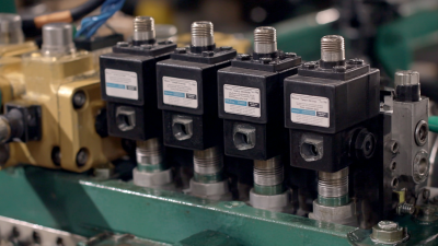
Technology adds options, but it does not remove basic engineering trade-offs. Solenoid, proportional, and cartridge valves each suit different layouts and control needs. Compare port size, pressure drop, fluid compatibility, temperature range, electrical connection, and available service support. Check the actual hydraulic schematic, too; a symbol on a drawing may hide installation constraints. Not always obvious. Contamination control deserves equal attention, because fine particles can cause sticking or erratic response. Ask how filtration, maintenance access, and replacement parts fit the real operating environment.
No checklist catches every installation quirk. Even an experienced buyer may overlook a connector, mounting pattern, or cold-start condition. Confirm critical values with the equipment maker or valve supplier, and review test data where available. This guide offers a practical way to compare choices, spot common mismatches, and ask better questions before specifying Hydraulic Valves for a new system or replacement.
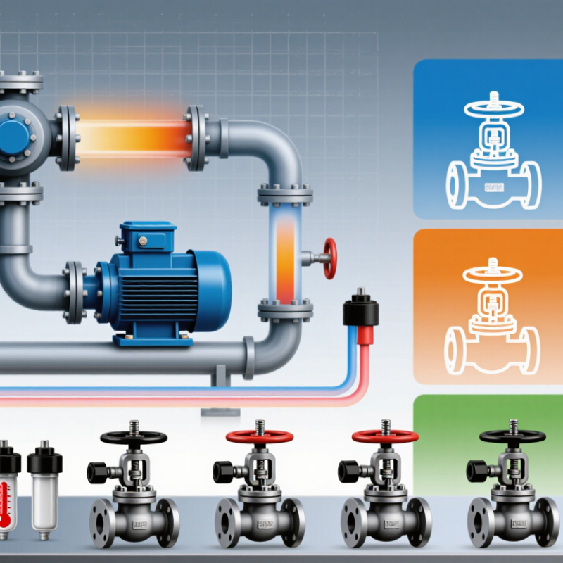
Hydraulic valves are the system’s traffic controllers: they direct flow, set pressure, and regulate actuator speed. A directional valve decides whether a cylinder extends, retracts, or holds. A pressure-control valve helps protect equipment from overload. Flow-control valves shape motion, but throttling can turn useful energy into heat. Small parts. Big consequences. On a machine, excess heat may show up as warm oil, slower cycles, and faster seal wear. Valve selection should begin with the circuit’s job, not just a catalog page.
Check rated pressure and flow against operating peaks, not only average figures. Then consider response time, leakage, contamination tolerance, mounting space, and safe access for testing. The U.S. Department of Energy’s Improving Pumping System Performance: A Sourcebook for Industry reports that pumping systems use nearly 20% of global electricity and 25–50% of energy in some industrial facilities. These figures describe pumping systems broadly, not hydraulic valves alone. Still, they underline why avoidable pressure drops and continuous throttling deserve attention. An oversized valve may seem forgiving, yet it can weaken low-flow control; an undersized one can raise pressure loss. I would also revisit the assumed duty cycle: field conditions rarely match a clean design spreadsheet. Measure before specifying.
| Valve type | Primary role in the system | Typical use or location | Key selection considerations | Practical selection note |
|---|---|---|---|---|
| Directional control valve | Starts, stops, and directs fluid flow to control actuator movement. | Between the pump, actuator, and tank; available in manual, solenoid, or pilot-operated designs. | Required flow and pressure, number of positions and ports, actuation method, spool configuration, and allowable leakage. | Check the valve’s flow paths in every position, including its neutral condition, against the circuit schematic. |
| Pressure relief valve | Limits system pressure by diverting excess flow when pressure reaches its setting. | Usually installed to protect a pump or pressure line, with flow routed to the tank or a low-pressure return. | Pressure setting, maximum flow, pressure override, response, return-line pressure, and heat generated while relieving flow. | Set the relief pressure within the limits of the weakest protected component; it is not a substitute for correct load control. |
| Pressure-reducing valve | Maintains a lower, controlled pressure in a branch circuit than in the main supply. | A branch supplying an actuator or component that needs lower pressure than the rest of the system. | Desired downstream pressure, flow range, pressure variation with flow, drainage requirements, and whether reverse flow must be handled separately. | Confirm the downstream circuit’s pressure requirement and the valve’s specified operating conditions. |
| Sequence valve | Allows flow to a secondary circuit after pressure reaches a defined threshold. | Circuits that need pressure-dependent sequencing, such as clamping before a machine operation. | Sequence pressure, required flow, leakage, drain arrangement, and interaction with the main relief setting. | Use the circuit design to confirm the intended order of operations and prevent unintended pressure buildup. |
| Flow-control valve | Adjusts flow to influence actuator speed; pressure-compensated designs help maintain flow as load pressure changes. | In a meter-in, meter-out, or bleed-off circuit, depending on the application and load behavior. | Required flow range, pressure drop, compensation needs, heat dissipation, and whether reverse flow is required. | Consider load changes and energy loss: throttling flow can generate heat and reduce system efficiency. |
| Check valve | Permits flow in one direction and restricts reverse flow. | Pump outlets, bypass paths, or lines where reverse flow needs to be blocked. | Cracking pressure, flow capacity, pressure drop, reverse leakage, and opening or closing behavior. | A standard check valve does not provide controlled load holding; use a suitable load-control arrangement where needed. |
| Counterbalance valve | Helps control an overrunning load and can help prevent a load from running ahead of pump flow. | Commonly used in actuator circuits for suspended or overrunning loads, such as lifting and lowering applications. | Load pressure, pilot ratio, flow, stability, pressure drop, and the actuator and hose arrangement. | Select and set it for the specific load and circuit; incorrect sizing or settings can cause unstable motion or excess heat. |
Selection reminder: Compare the valve’s rated pressure and flow with the circuit’s operating and peak conditions. Also check fluid compatibility, temperature and viscosity limits, contamination-control requirements, port or mounting standard, response needs, and service access. Final limits and settings should be verified against the selected valve’s technical documentation and the system design.


 Send Inquiry


