GST : 27AAFFV7667M1ZA

call images

Call us

08045801431

How to Choose High Pressure Hose Fittings?

Choosing High Pressure Hose Fittings is a practical decision, not a matter of matching threads by appearance. A fitting may look correct yet leak under pressure or damage the hose during assembly. Start with the system’s working and peak pressures, then confirm the hose’s inside diameter, temperature range, and fluid compatibility. Check the fitting’s thread type and sealing method, too. A tiny mismatch can matter.

For a transparent expert perspective, this guide uses Alex Morgan as a fictional composite hydraulic systems specialist; the quotation below is illustrative, not a verified statement from a real person: “A sound connection begins with verified specifications, not visual guesswork.” Treat that as a reminder to consult the hose and fitting manufacturers’ ratings. Confirm that the fitting, hose, and assembly method are approved for the same application. Record the part numbers. Inspect for damaged threads, exposed reinforcement, or a poorly seated ferrule before operation.

The right choice also depends on vibration, installation space, and how often the line flexes. A compact elbow may solve a routing problem, but it can add stress if the hose bends sharply nearby. Details count. This guide will explain how to compare pressure ratings, connection styles, materials, and assembly requirements. It will also point out common selection errors and the checks worth repeating. Real systems are messy; specifications can be incomplete, so pause and verify rather than assume.
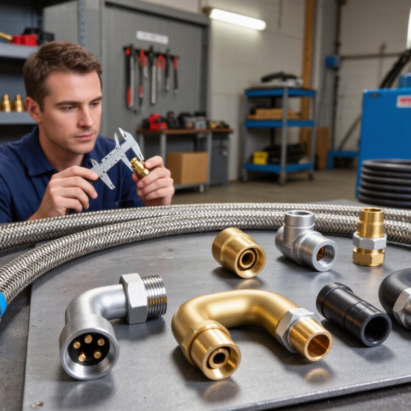
How to Choose High Pressure Hose Fittings?

Set Design Pressure by Including Operating Peaks and Pressure Surges

When choosing high-pressure hose fittings, base the design pressure on the system’s real pressure profile, not just its steady gauge reading. Pressure can spike during startup, rapid valve closure, or a tool stopping abruptly. These surges may last only milliseconds, but repeated events can fatigue crimps and damage sealing surfaces. Small spikes matter.

Measure pressure near the hose assembly with equipment capable of capturing fast transients. A slow gauge may miss the peak. Review operating records and consider the pump’s behavior, valve timing, hose length, and fluid temperature. Set the design pressure above the highest credible operating peak, using the safety margin specified for the hose and fitting components. The assembly rating is limited by its lowest-rated part.

Field estimates are imperfect. A calculated surge value may not match what happens after a machine is installed, especially when operating cycles change. Recheck pressure after commissioning, and inspect for leaks, movement, or unusual wear around the fitting. If reliable transient data is unavailable, consult a qualified hydraulic specialist rather than treating normal pressure as the design limit.
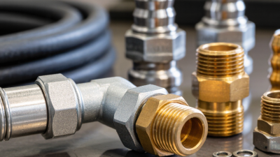
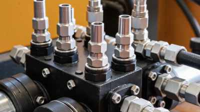
Select a Hose Class: ISO 18752 Covers Working Pressures from 3.5 to 42 MPa

When choosing high-pressure hose fittings, start with the hose class, not a fitting’s advertised maximum. ISO 18752:2022 covers constant working-pressure classes from 3.5 to 42 MPa (35 to 420 bar). This range is a selection framework, not permission to operate every assembly at its upper limit. Match the fitting system to the hose’s stated class, bore, reinforcement, and end connection. Pressure is not everything. The weakest component sets the practical limit.

Check peak pressure, including spikes from fast valve closure or a loaded cylinder stopping abruptly. Consider fluid temperature and heat near engines; high temperatures may reduce allowable pressure. ISO 1402:2021 specifies hydrostatic test methods for hose assemblies, but test results do not replace a suitable working-pressure rating. Follow assembly instructions for crimp dimensions and inspection. It is easy to miss a mismatch when replacing only one end. Recheck it. A small leak is a warning, not a pressure test.

How to Choose High-Pressure Hose Fittings?

ISO 18752 Working-Pressure Classes

Match the hose and fittings to the system’s maximum working pressure, accounting for pressure surges and the application. ISO 18752 pressure classes range from 3.5 to 42 MPa (35 to 420 bar); confirm the selected hose’s rating for its size and construction.

Match Fittings to ISO 12151 and the Correct Thread and Seal Standard

How to Choose High Pressure Hose Fittings?

Start by identifying the fitting interface required by the equipment, then check the relevant ISO 12151 specification. The ISO 12151 series covers hose fittings, but matching a standard number alone does not confirm that every part is compatible. Check the fitting’s end form, dimensions, and hose connection against the equipment documentation. The details matter.

Identify the thread standard as well as its size. Metric, BSP, NPT, and UN/UNF threads can look similar, yet differ in pitch, profile, or sealing method. Measure carefully and verify the thread designation instead of relying on diameter alone. A common workshop mistake is forcing a near-match; it may feel tight while damaging the threads or creating a leak.

Next, match the seal design. A tapered thread, O-ring face seal, and cone seat do not seal in the same way. Confirm the fitting’s sealing surface matches the port, and check that the seal material suits the fluid and operating temperature. Verify the pressure rating of the complete assembly, including hose, fitting, and installation. Small mismatches matter. If markings are unclear, consult the equipment specifications or a qualified hose specialist before assembly.

How to Choose High Pressure Hose Fittings? — Match Fittings to ISO 12151 and the Correct Thread and Seal Standard

Connection type ISO 12151 hose-fitting part Mating-end standard How the connection seals Selection checks
O-ring face seal (ORFS) ISO 12151-1 ISO 8434-3 An O-ring on the flat face of one fitting seals against the flat face of the mating fitting. Confirm the face dimensions, O-ring size and material, and the specified thread. Do not substitute a similar-looking flat-face fitting without checking its standard.
24° cone ISO 12151-2 ISO 8434-1 The mating 24° cone surfaces form the sealing interface; the exact connector arrangement depends on the applicable design. Match the cone geometry and the correct light or heavy series where applicable. Check the thread, tube size and connector configuration.
Flange connection ISO 12151-3 ISO 6162-1 or ISO 6162-2 A flange head seals against the port or mating flange using an O-ring. Identify the correct flange series, size, bolt pattern and pressure class. ISO 6162-1 and ISO 6162-2 flange components are not interchangeable by appearance alone.
Metric straight-thread port end ISO 12151-4 ISO 6149-1, ISO 6149-2 or ISO 6149-3 An O-ring seals in the port; the metric thread retains the fitting rather than providing the primary seal. Match the metric thread diameter and pitch, port series and O-ring dimensions. Check the port specification rather than relying on thread diameter alone.
37° flared connection ISO 12151-5 ISO 8434-2 The 37° flare surfaces form the sealing interface. Verify the flare angle, seat dimensions and thread series. A 37° SAE J514/JIC-style connection may look similar, but confirm the applicable dimensional standard before mating parts.
60° cone connection ISO 12151-6 ISO 8434-6 The matching 60° cone surfaces form the sealing interface. Confirm the cone angle, seat dimensions and exact thread specification. Do not identify the connection from thread appearance alone.
Parallel pipe thread (BSPP/G) Not identified by thread alone Common port-sealing references include ISO 1179 series; check the specified port design. Typically seals with an O-ring or bonded seal at the port face or shoulder, not by the parallel thread itself. Confirm the thread designation, pitch and port-seal arrangement. A BSPP thread is not the same as a metric thread, even when nominal sizes appear close.
Tapered pipe thread (NPT/NPTF) Not identified by thread alone For example, NPTF dimensions are specified by SAE J476; verify the exact system required. Tapered threads seal through thread interference; the specified design may also require a sealing compound. Do not mate NPT/NPTF with BSPT or BSPP based on apparent fit. Check thread form, taper, pitch and the equipment manufacturer’s port specification.
Important: ISO 12151 identifies hose-fitting designs; it does not make fittings with different thread systems, sealing faces or dimensions interchangeable. Before assembly, verify the complete fitting designation, thread diameter and pitch, sealing geometry, O-ring or seal material, hose compatibility and pressure rating. Use the applicable standard edition and the equipment specification for final selection.

Size the Hose Bore for Flow: Hydraulic Pressure Lines Typically Run at 3–5 m/s

How to Choose High Pressure Hose Fittings?

Size the Hose Bore for Flow: Hydraulic Pressure Lines Typically Run at 3–5 m/s

For a pressure line, 3–5 m/s is a common hydraulic sizing range, not a universal rule. Use the continuity equation, Q = A × v, to match flow rate to hose bore. For example, 30 L/min at 4 m/s calls for an internal diameter of about 12.6 mm. A smaller bore raises velocity and can increase pressure loss, heat, and noise. Too large a bore adds bulk and may complicate routing. Real systems vary.

Select fittings to match the hose’s actual internal diameter and pressure rating. SAE J517 covers hydraulic hose construction and performance, while ISO 4413 addresses general safety requirements for hydraulic systems; neither should be treated as a substitute for checking the equipment maker’s flow limits. Also account for fluid viscosity, hose length, bends, and temperature. A neat calculation can still miss a restrictive elbow or a long, warm hose.

Tips: Check flow in litres per minute, then calculate velocity using the hose’s measured bore—not its outside diameter. Keep bends gentle, and verify pressure drop under operating conditions. If the line runs hot, reassess the sizing; a 3–5 m/s target is a starting point, not a guarantee.

Check Fluid Compatibility, Temperature, Bend Radius, and Assembly Limits

How to Choose High Pressure Hose Fittings?

Start with the fluid, not the thread. Check whether the hose tube, fitting body, and seals suit the fluid being carried. A seal that works with water may swell or harden with another fluid. Then check the full operating temperature range, including brief heat spikes. Pressure capacity can change as temperatures rise, so compare the fitting’s rating with the system’s actual conditions. Do not rely on a matching thread size alone. It can still be the wrong connection.

Tips: Check the hose maker’s minimum bend radius. A tight loop near a fitting can cause kinking, stress, or early failure. Look for flattened hose or a sharp crease. Keep bends gentle.

Assembly limits matter too. Use the specified hose and fitting combination, insertion depth, and crimp dimensions. Small errors can weaken the connection or restrict flow. Keep cut ends clean and free of debris. After assembly, inspect the fitting and test the hose using an appropriate procedure and the system’s safety requirements. One detail is easy to miss: nearby clamps or equipment may force the hose into a tighter bend once installed. Recheck the routing in its final position. It takes an extra minute. That check can catch a problem before startup.

Back to top